Smart Gardening System Project Documentation .
Project Venue: DIY Lab Premises(Kothrud)
Team Members: Sakib,Vishal, Pandurang ,Balaji,Kantrao,Ashish,Sachin,Sabmit & Hariom
Date: 01/04/2025
Survey and Initial Planning -
Objective:
The primary goal of today’s work was to survey the existing garden structure and plan the requirements for plant selection, soil assessment, and irrigation system setup.
Tasks Completed -
Garden Structure Analysis
Conducted a detailed survey of the existing garden layout.
Identified areas for plant placement and pipeline installation.
Plant Requirement Calculation
Counted the number of plants required:
16 plants for ground planting.
2 plants for pot placement.
Decided on the arrangement of plants based on aesthetic and functional needs.
Soil Analysis & Plant Selection
We used Geo Map and Google Lens to examine the soil quality and type.
Researched plant species suitable for the soil conditions via online resources.
Irrigation System Planning
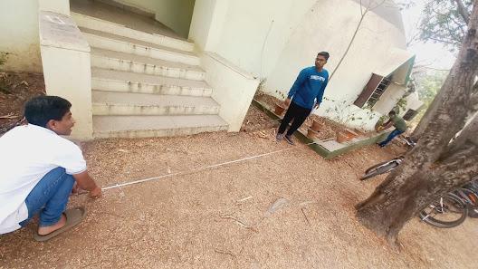
Measured the total length of pipe required using a measuring tape.
Calculated the total pipeline length needed: 98 meters.
Determined the optimal pipeline layout to ensure efficient watering.
Observations & Key Findings -
Checked the availability of basic tools required for cleaning and structuring the garden.
- The existing garden has enough space for planned plants and irrigation setup.
The soil conditions were analyzed to ensure plant compatibility.
The pipeline system needs 98m of pipes to cover the garden area efficiently.
- Implemented a two-way supply system for the garden because we use two-way water supply system the garden’s right side has a slope, and water from one endcouldn’t reach the other side properly. So, we supplied water from both sides spread it evenly.
- Right side: 50m of pipe required for half the garden.Left side: 48m of pipe required for the remaining garden.
Measuring the total length of the pipeline -

Deciding the total count of pots and plants -
End of Day 1 Report
----------------------------------------------------------------------------------------------------------------------------------------
Date: 02/04/2025
Garden Cleaning and Maintenance -
Objective:
The main focus of today’s work was to clean the garden, remove unwanted tree leaves, and organize gardening materials using the necessary tools.
Tasks Completed -
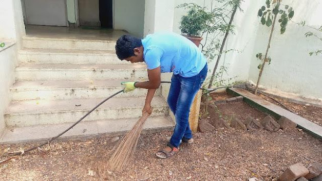
Garden Cleaning
Cleared the garden of unwanted debris, including dried leaves and other waste.
Collected all unwanted tree leaves from the ground and set them aside for further use.
Utilization of Gardening Tools
Used the necessary tools for efficient cleaning and maintenance, including:
Gardening tools for manual cleaning and maintenance.
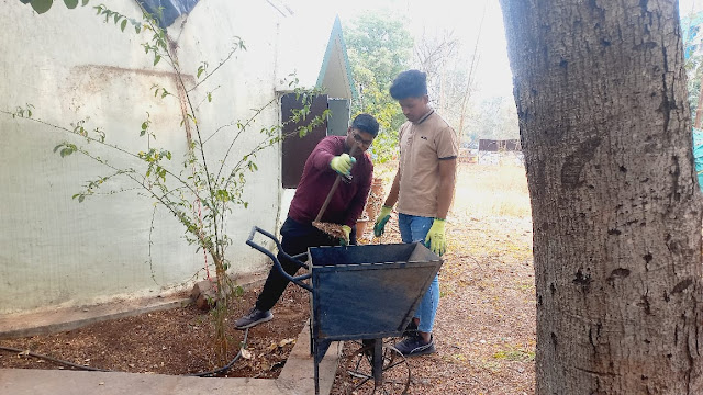
Two-Wheel Mini Construction Trolley to transport collected materials.
Broom for sweeping and final cleaning.
Plastic pots to carry and dispose of collected leaves.
Waste Management & Organization
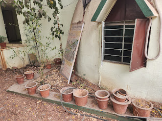
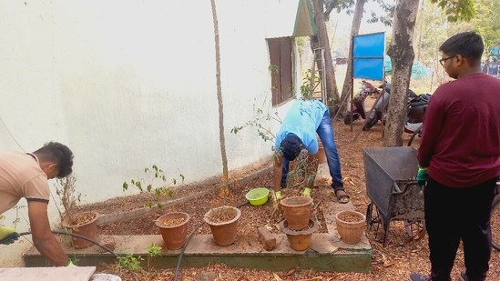
Gathered all unwanted pots and moved them to a designated corner for future use.
Collected tree leaves and stored them for biogas production, which will be utilized during new plant plantation.
Team Collaboration -
Successfully completed the cleaning process with the guidance and help of the project coordinator (Tejswini Tai).
Observations & Key Findings -
The garden is now well-cleaned and prepared for the next steps in the project.
Proper organization of unwanted materials ensures a more structured workspace.
The use of biogas from collected leaves contributes to an eco-friendly approach.
Collecting the unwanted leaves from the tree using a trolley -
Date: 03/04/2025
Garden Arrangement & Final Design -
Objective -
The main goal of today’s work was to rearrange the existing plants, structure the bricks, finalize the garden design, and loosen the soil using agricultural machinery to ensure better plant growth and an organized layout.
Tasks Completed -
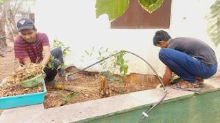
Plant Rearrangement -
Carefully moved and repositioned the existing plants to enhance their placement.
Ensured each plant had adequate space for healthy growth.
Adjusted plant positions to improve both the aesthetic appeal and functionality of the garden.
Brick Structuring -
Arranged bricks to define pathways and create borders around plant sections.
Ensured bricks were properly aligned to maintain stability and neatness.
Used proper spacing and positioning to enhance the overall appearance of the garden.
Final Garden Design -
Used gardening tools to refine the structure and layout of the garden.
Defined separate areas for plants, pathways, and open spaces for easy access.
Made improvements to ensure the garden is well-organized and visually appealing.
Soil Preparation -
Used an agricultural machine to loosen the soil, making it more suitable for plant growth.
Ensured the soil was aerated and properly mixed to improve water absorption and root health.
Removed hard soil patches to create a more fertile ground for plants.
Observations & Key Findings -
The rearrangement of plants has improved their placement and overall organization.
Brick structuring has defined clear pathways and borders, making the garden more structured.
Loosening the soil has enhanced its quality, ensuring better plant growth.
The final design of the garden is well-organized, visually appealing, and easy to maintain.
End of Day 3 Report
-----------------------------------------------------------------------------------------------------------------------------
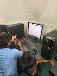
Date: 04/04/2025
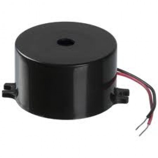
Arduino and Soil Moisture Sensor Connection and Testing -
Objective -
The objective of today’s work was to build and test a soil moisture detection system using Arduino,
a Soil Moisture Sensor, and a Buzzer, and to verify the system's response using wet and dry soil samples.
Tasks Completed -
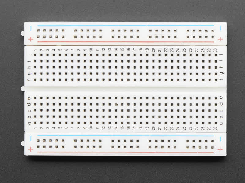
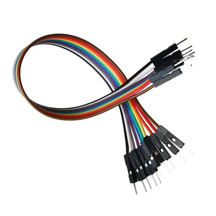
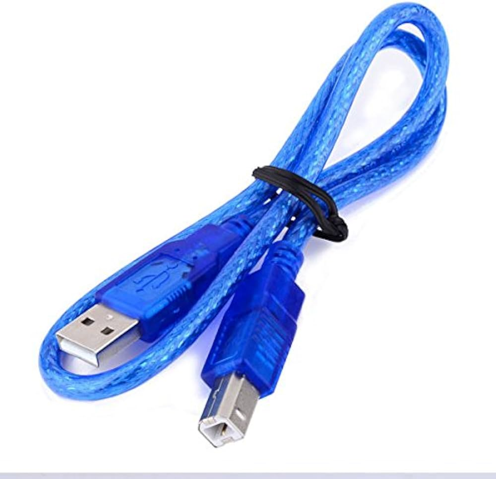
Component Preparation
Gathered all required components:
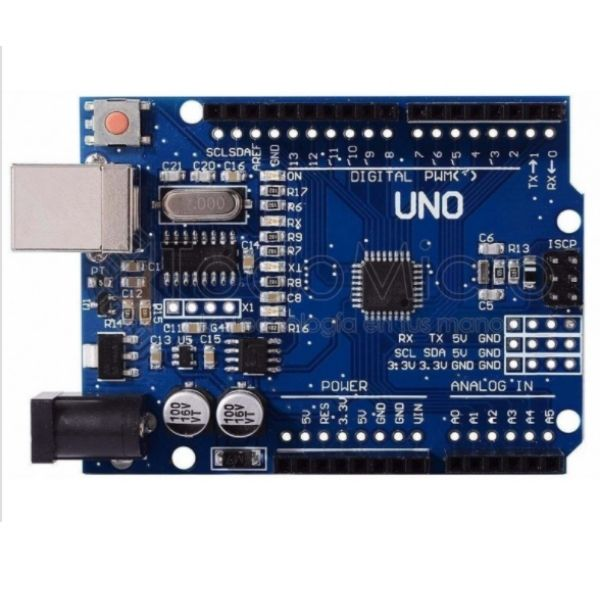
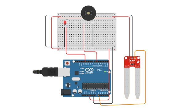
Arduino Uno
Breadboard
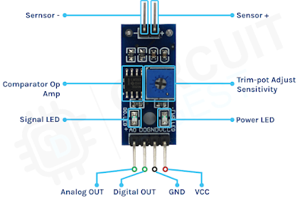
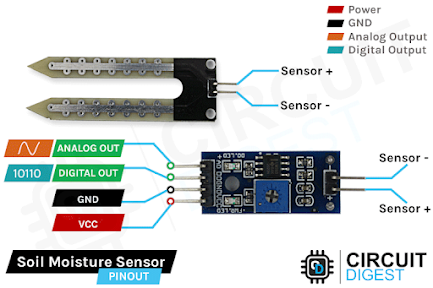
- Soil Moisture Sensor
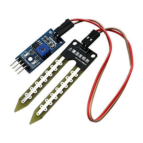
- Buzzer
- Jumper Wires
- USB Cable for Programming
- Soldering Iron and Solder Wire
- Checked and verified that all components were functional.
Code Uploading -
Wrote and uploaded the program/code to the Arduino before connecting the Soil Moisture Sensor and other components.
Ensured the correct logic:
If the soil is wet, the buzzer should turn ON.
If the soil is dry, the buzzer should stay OFF.
Used the USB Cable to connect Arduino to the laptop for code uploading.
CODE -
// Define the pin for the moisture sensor and pump
const int moistureSensorPin = A0; // Moisture sensor connected to analog pin A0
const int pumpPin = 2; // Water pump connected to digital pin 8 (via relay)
// Set moisture threshold value
const int lowMoistureThreshold = 200; // Adjust this value based on your sensor's calibration
const int highMoistureThreshold = 950;
void setup() {
Serial.begin(9600); // Start serial communication
// Set the pump pin as output (for relay control)
pinMode(pumpPin, OUTPUT);
// Initially turn off the pump (relay will be in "NO" state)
digitalWrite(pumpPin, LOW);
}
void loop() {
// Read the moisture level from the sensor
int moistureValue = analogRead(moistureSensorPin);
// Print the moisture value to Serial Monitor
Serial.print("Moisture Value: ");
Serial.println(moistureValue);
// Control the pump based on moisture level
if (moistureValue < lowMoistureThreshold) {
digitalWrite(pumpPin, HIGH); // Turn on the pump (relay switches to "COM")
Serial.println("Pump ON - Soil is Dry!");
} else {
digitalWrite(pumpPin, LOW); // Turn off the pump (relay goes back to "NO")
Serial.println("Pump OFF - Soil is Wet.");
}
\
Serial.println("----------");
delay(1000); // Wait 1 second before the next reading
}
Circuit Assembly -
After successful code upload, carefully connected components on the Breadboard:
Soil Moisture Sensor connected to Arduino analog input pins via breadboard.
Buzzer connected to digital output pin using jumper wires.
Ensured proper power (VCC and GND) connections for all components.
Performed soldering for critical joints to provide strong connections and avoid loose wiring.
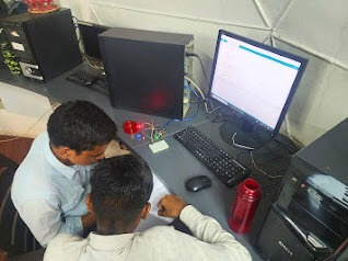
Testing with Soil Samples -
Prepared two separate cups:
One containing wet soil.
One containing dry soil.
Inserted the Soil Moisture Sensor into each cup:
Wet Soil: Buzzer turned ON indicating moisture detected.
Dry Soil: Buzzer remained OFF showing no moisture.
Repeated tests to verify consistent performance.
Verification and Final Adjustments -
Checked sensor readings through Arduino Serial Monitor.
Fixed minor loose connections on the breadboard.
Confirmed the system is stable and reliable for further use.
Observations & Key Findings -
Uploading code before connecting the sensor prevented possible short-circuits and ensured
safe operation.
The soil moisture sensor responded accurately to the moisture levels.
Buzzer and sensor both worked without delay or malfunction.
The final circuit was compact, safe, and functional.
End of Day 4 Report
-----------------------------------------------------------------------------------------------------------------------------
Date: 07/04/2025
Main Pipeline and Drip Line Measurement and Finalization -
Objective -
Today's work focused on completing measurements for the main connection pipe and dripping pipes, finalizing the type of pipes and connectors required, and creating a detailed material list for procurement.
Tasks Completed -
Main and Drip Pipe Measurement -
Measured the total length required for the main connection pipe.
Measured the total length needed for the drip pipes covering all plant areas.
Connector Planning -
Counted the number of connectors (e.g., elbow connectors, T-joints, straight connectors)
required for proper setup.
Finalization of Materials -
Finalized the type of main pipe to be purchased, ensuring durability and suitability for
garden use.
Finalized the type of connectors and other plumbing-related materials like:
Elbow connectors
T-joints
Straight connectors
End caps
Material List Preparation -
Created a complete list of all pipes, connectors, and additional plumbing items needed for purchase.
Sample Collection -
Collected pipe samples to make it easier to match and purchase the correct type of connectors and fittings.
Online Research -
Researched online (Google search) to find good quality connectors and pipes
(KS connectors and similar types) suitable for the irrigation system.
Nozzle Calculation -
Counted the total number of nozzles needed for the drip irrigation system to
ensure every plant receives adequate water supply.
Observations & Key Findings -
Proper measurement ensures minimal wastage of materials during installation.
Collecting pipe samples will simplify purchasing compatible connectors and fittings.
Finalizing the quality and type of pipes/connectors now helps in smoother future setup
and reduces chances of mismatch.
A clear list of material requirements is now ready for the next steps.
Next Plan -
Visit the market to analyze product cost and quality for pipes, connectors, and other materials.
End of Day 5 Report
----------------------------------------------------------------------------------------------------------------------------------------
Date: 08/04/2025
Market Survey and Partial Material Procurement -
Objective -
Today's work focused on surveying the local market to purchase the required materials listed earlier for the garden project and analyzing the availability and quality of products.
Tasks Completed -
Market Visit -
Visited local hardware shops and garden supply stores to find the materials listed previously.
Checked the availability of important items like drippers, drip pipes, connectors, and plumbing accessories.
Product Availability Check -
Observed that several required materials (drippers, dripping pipes, connectors) were not available in local shops as per project specifications.
Identified a limited variety and quality for irrigation-specific materials in the market.
Material Purchase -
- Successfully purchased the hose pipe from the local market after confirming quality and suitability.
Decided not to compromise on other critical materials and opted to purchase them through
online platforms for better quality and availability.
Decision on Remaining Materials -
Finalized the decision to buy remaining items like:
Drippers
Drip Pipes
Connectors (elbow connectors, T-joints, straight connectors, end caps)
Plan to select products from online stores after reviewing quality and cost.
Observations & Key Findings -
Local market lacks the required range and quality of drip irrigation components.
Buying hose pipe from the market was feasible because quality verification was possible in
person.
Online platforms offer a better range and specification match for drip irrigation needs.
Strategic selection of materials now will help in efficient installation and better garden
performance.
Next Plan -
Purchase the remaining materials (drippers, drip pipes, connectors, nozzles) via online
platforms after detailed analysis of cost and quality.
End of Day 6 Report
-----------------------------------------------------------------------------------------------------------------------------
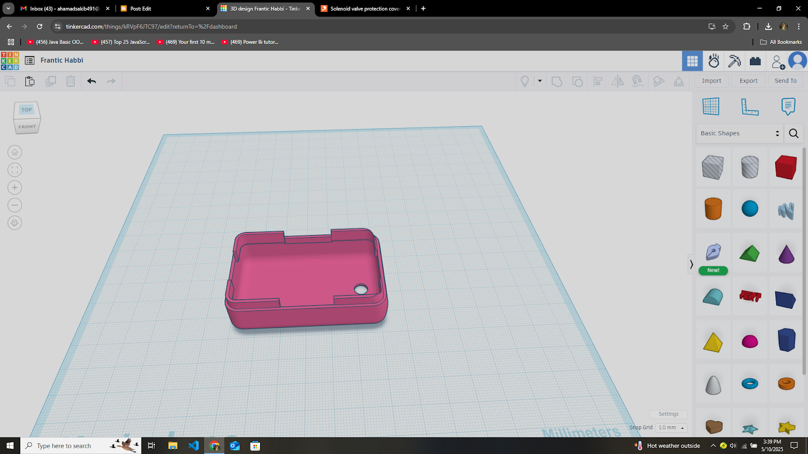
Date: 11/04/2025
Casing Design for Soil Moisture Sensor -
Objective -
Tasks Completed -
Design Discussion -
Initially, we discussed different ideas and concepts for the casing. The goal was to create a compact, lightweight, and durable cover that would not obstruct the sensor’s functionality.
Measurement and Planning -
We measured the width, height, and depth of the soil moisture sensor carefully to ensure the
casing design would fit perfectly without hampering sensor readings.
Casing Design Using Tinker CAD -
Using Tinker CAD software, we created a 3D model of the casing based on the discussed design.
The casing was made considering -
Proper openings at the sensing area for soil contact.
Closed protection for the sensitive electronics and connectors.
A simple structure easy to manufacture using 3D printing or manual crafting.
Prototype Finalization -
After a few adjustments in design dimensions, we finalized a prototype that securely holds the
sensor and provides robust protection.
Observations & Key Findings:
It is important to allow the sensor tips to remain exposed while fully covering the rest of the
circuit parts.
Tinker CAD is a useful and beginner-friendly tool for quick prototyping and making design
adjustments easily.
Accurate measurement beforehand saved time during the digital design phase.
A good casing design can significantly extend the sensor’s working life when used in outdoor
soil conditions.
End of Day 7 Report
-----------------------------------------------------------------------------------------------------------------------------
Date: 12/04/2025
Placement Planning for Main Connection Box (Wi-Fi Connectivity)
Objective:
Today's goal was to decide the suitable locations for placing the main connection box, which connects the
project’s circuits to Wi-Fi. The decision was made based on Wi-Fi range, environmental protection, and
convenience for future maintenance.
Tasks Completed:
- goog_1060524997
Wi-Fi Range Testing:
Tested the Wi-Fi signal strength across different areas of the garden to find locations - where the connectivity is strong and stable. Identified two suitable spots with optimal
- signal reception.
Location Selection:
Based on the Wi-Fi range test, we shortlisted two places for installing the main circuit box.- These spots ensure uninterrupted Wi-Fi connectivity, which is critical for real-time data
- transfer and remote monitoring.
Environmental Safety Check:
Examined each selected location for potential environmental threats:Ensured that water flow during rainfall would not directly hit the box.
Checked nearby structures and natural elements (like trees and shades) to
- provide some protection from rain and direct sunlight.
Assessed ground levels to avoid placement in areas prone to water accumulation.
Finalization of Mounting Plan:
Decided that the connection box would be mounted at a height safely above ground- level to prevent damage due to waterlogging. Also planned to use waterproof casing for
- additional protection.
Observations & Key Findings:
Strong Wi-Fi range is available only in limited parts of the garden; careful selection of
placement is crucial.
Environmental protection like rain shielding and safe elevation is necessary to avoid
damage to electronic components.
Early planning of location and protection helps reduce maintenance issues later and
increases the project’s reliability.
End of Day 8 Report
-----------------------------------------------------------------------------------------------------------------------------
The MIT App Inventor AND smart Garden-2
Benefits of a Smart Garden
Water Conservation: Smart irrigation systems reduce water usage by watering plants
only when necessary.
Convenience: Automatic watering, lighting, and climate control make plant
care easier and less time-consuming.
Healthier Plants: Sensors help you keep track of essential factors like soil moisture,
temperature, and sunlight to ensure plants thrive.
Energy Efficiency: Some systems optimize the use of energy, reducing electricity
bills, especially in indoor gardens.
Remote Monitoring: You can monitor and adjust your garden remotely via mobile apps.
Programming on Arduino IDE.
Uploading Arduino code to the board and testing it.
Arduino code in MIT App
// Define the pin for the moisture sensor and pump
const int moistureSensorPin = A0; // Moisture sensor connected to analog pin A0
const int pumpPin = 2; // Water pump connected to digital pin 8 (via relay)
// Set moisture threshold value
const int lowMoistureThreshold = 200; // Adjust this value based on your sensor's calibration
const int highMoistureThreshold = 950;
void setup() {
Serial.begin(9600); // Start serial communication
// Set the pump pin as output (for relay control)
pinMode(pumpPin, OUTPUT);
// Initially turn off the pump (relay will be in "NO" state)
digitalWrite(pumpPin, LOW);
}
void loop() {
// Read the moisture level from the sensor
int moistureValue = analogRead(moistureSensorPin);
// Print the moisture value to Serial Monitor
Serial.print("Moisture Value: ");
Serial.println(moistureValue);
// Control the pump based on moisture level
if (moistureValue < lowMoistureThreshold) {
digitalWrite(pumpPin, HIGH); // Turn on the pump (relay switches to "COM")
Serial.println("Pump ON - Soil is Dry!");
} else {
digitalWrite(pumpPin, LOW); // Turn off the pump (relay goes back to "NO")
Serial.println("Pump OFF - Soil is Wet.");
}
\
Serial.println("----------");
delay(1000); // Wait 1 second before the next reading
}
Applications of IoT
Smart Homes: Thermostats, lights, and security systems that you can control
with your phone.
Healthcare: Wearables that monitor heart rate, oxygen levels, and physical activity.
Industrial IoT : Machinery maintenance, production line automation, and energy
management.
Smart Cities: Traffic control, waste management, and environmental monitoring.
Code for Soil moisture sensor:
const int relayPin = 7;
const int moisturePin = A0;
void setup() {
pinMode(relayPin, OUTPUT);
pinMode(moisturePin, INPUT);
pinMode(relayPin, OUTPUT);
digitalWrite(relayPin, HIGH);
Serial.begin(9600);
}
void loop() {
int moistureValue = analogRead(moisturePin); // Read value from sensor
Serial.println(moistureValue);
delay(2000);
if (Serial.available() > 0) {
char command = Serial.read();
if (command == 'A') {
digitalWrite( relayPin ,LOW);
}
else if (command == 'a') {
digitalWrite(relayPin, HIGH);
}
}
}
-----------------------------------------------------------------------------------------------------------------------------
Date: 8th May 2025
Title: Water Supply Integration and Drip Irrigation Setup
Objective:
Today's objective was to initiate and complete the integration of the Hose pipe with the garden’s water supply system, evaluate water pressure and flow, determine appropriate drip pipe specifications, and identify a suitable protective solution for the solenoid valve. These tasks are foundational for the efficient functioning of the smart
irrigation system.
Tasks Completed:
1. Connecting the Hose Pipe to the Water Supply
The first critical task involved establishing a secure and leak-free connection between the Hose pipe and the main garden water source.
Materials Used:
Hose pipe

Hose connectors
Pipe fittings (couplings, elbows, tees)
Pipe clamps
Steps Taken:
Identified the primary outdoor faucet as the connection point.
Measured and cut the Hose pipe to the required length for optimal reach.
Fitted necessary pipe connectors to establish a firm and reliable joint.
Secured the pipe using clamps to prevent movement and disconnection during water flow.
2. Water Supply Pressure and Flow Check
Ensured that the water supply is adequate and consistent for the upcoming irrigation system.
Steps Taken:
Used a pressure gauge to confirm a steady pressure of approximately 45 psi—well within the
ideal range for drip systems (30–50 psi).
Conducted a flow rate test using a 5-gallon bucket, verifying sufficient flow for planned irrigation
needs.
Ran the water supply for 15 minutes continuously to monitor consistency—no pressure
drops or irregular flow detected.
3. Drip Pipe Diameter Selection
Choose the appropriate pipe diameter to ensure optimal water distribution across the garden.
Pipe Diameter:
Selected 1/2-inch diameter drip pipe to accommodate the garden's medium size and
ensure effective pressure balance.
4. Sourcing Solenoid Valve Cover for Protection
Instead of installing, today's focus was on identifying a suitable protective cover design for the solenoid valve.
Steps Taken:
Searched online and found STL files for a waterproof solenoid valve cover designed to shield
components from water and weather.
Imported the STL files into Tinker CAD to assess design dimensions, ventilation slots, and
compatibility with the existing valve setup.
Evaluated potential for 3D printing the cover using weather-resistant materials.
Observations & Key Findings:
A secure connection between the Hose pipe and water supply is critical to avoid leaks and
pressure drops.
Accurate pressure and flow measurement ensure system efficiency and prevent under- or
over-watering.
Pipe sizing must be selected according to garden layout and system scale for optimal pressure
distribution.
Using tools like Tinker CAD to evaluate STL models supports precise and efficient hardware
integration.
-----------------------------------------------------------------------------------------------------------------------------
Date: 9th May 2025
Title: Design, Preparation, and 3D Printing of Solenoid Valve Protective Cover
Objective:
The primary goal for today was to finalize the design of a custom protective cover for the solenoid valve,
ensure compatibility through precise measurements, and complete the 3D printing process.
The printed cover aims to shield the valve from environmental exposure and ensure long-term
durability of the irrigation control system.
Tasks Completed:
1. Final Selection and Design of the Solenoid Valve Cover
After evaluating various options, a suitable solenoid valve cover design was finalized and customized.
Steps Taken:
Selected the most appropriate design concept based on durability, fit, and ease of maintenance.
Used Tinker CAD to create a precise model of the cover, incorporating actual valve dimensions
to ensure a snug fit.
Verified features such as ventilation slots and mounting flexibility.
Completed and finalized the design using accurate scaling and measurements.
We designed a 3D cover for the solenoid valve in Tinker CAD to protect it from water
2. Exporting the STL File for 3D Printing
Prepared the finalized design for 3D printing.
Steps Taken:
Exported the finished model from Tinker CAD in .STL file format, compatible with 3D slicing
software.
Ensured that the STL file met quality standards and had no mesh or scaling issues before slicing.
3. 3D Print Preparation Using Orca Slicer
The STL file was imported and adjusted for the actual print setup.
Steps Taken:
Opened the STL file in Orca Slicer application.
Oriented the model appropriately on the print bed to ensure proper support and print quality.
Adjusted the scale and position to fit within the dimensions of the 3D printer bed.
Sliced the file and saved the print-ready G-code onto a USB flash drive.
4. 3D Printing and Fit Testing
Executed the 3D printing and validated the fit and usability of the printed cover.
Steps Taken:
Inserted the USB drive into the 3D printer and started the print using the prepared G-code.
Monitored the print process to ensure there were no interruptions or material issues.
Upon completion, carefully removed the printed solenoid cover.
Tested the printed cover by placing it over the actual solenoid valve—it fit perfectly and
provided full protection as intended.
Observations & Key Findings:
Designing the cover directly in Tinker CAD allowed for precise control over dimensions,
leading to a perfect first-time fit.
Using Orca Slicer ensured accurate scaling and proper bed placement, improving print
efficiency and minimizing material waste.
The printed cover aligns well with the solenoid valve and offers both water protection and
ventilation, fulfilling its functional and structural requirements.
-----------------------------------------------------------------------------------------------------------------------------
Date: 10th May 2025
Title: Circuit Design and Control Setup for Solenoid Valve Using XIAO
Board and Arduino Cloud:
Objective:
The goal for today was to build and test a circuit that enables remote control of the solenoid valve using a XIAO microcontroller, relay module, and Arduino Cloud integration.
This setup forms the core of the automated irrigation control system, allowing water flow to be toggled through an online dashboard.
Tasks Completed:
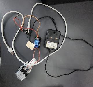
1. Component Selection and Setup
Components:
XIAO Board (microcontroller)

Relay module
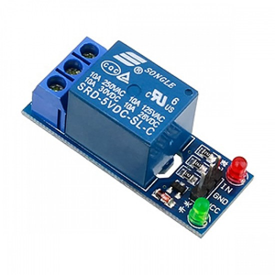
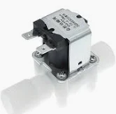
Solenoid valve
Jumper wires

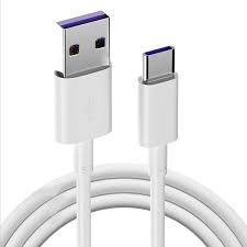
USB cable
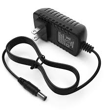
12V Adapter (for solenoid valve power supply)
2. Circuit Design and Assembly
Designed and wired the electronic circuit to control the solenoid valve through the relay using the XIAO board.
Steps Taken:
Connected the relay to the XIAO board using jumper wires.
Wired the solenoid valve to the relay output terminals.
Provided a 12V DC power supply to the solenoid valve using an adapter.
Powered the XIAO board via USB cable.
Configured the relay to act as a digital switch for controlling the solenoid valve's power.
Circuit :-


- XIAO board circuit connections
3. Arduino Cloud Configuration
Configured the Arduino Cloud environment to remotely control the relay via internet-based dashboards.
Steps Taken:
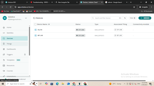
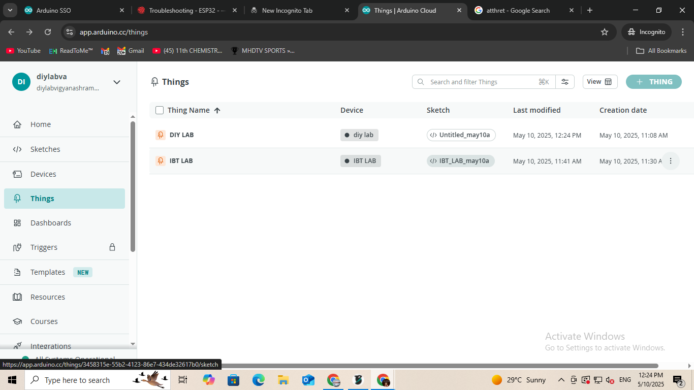
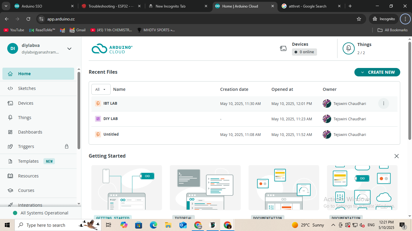
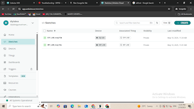
Logged into Arduino Cloud and created two projects: DIY LAB and IBT LAB.
For each project, created a separate variable: relay1 for DIY LAB and relay2 for IBT LAB.
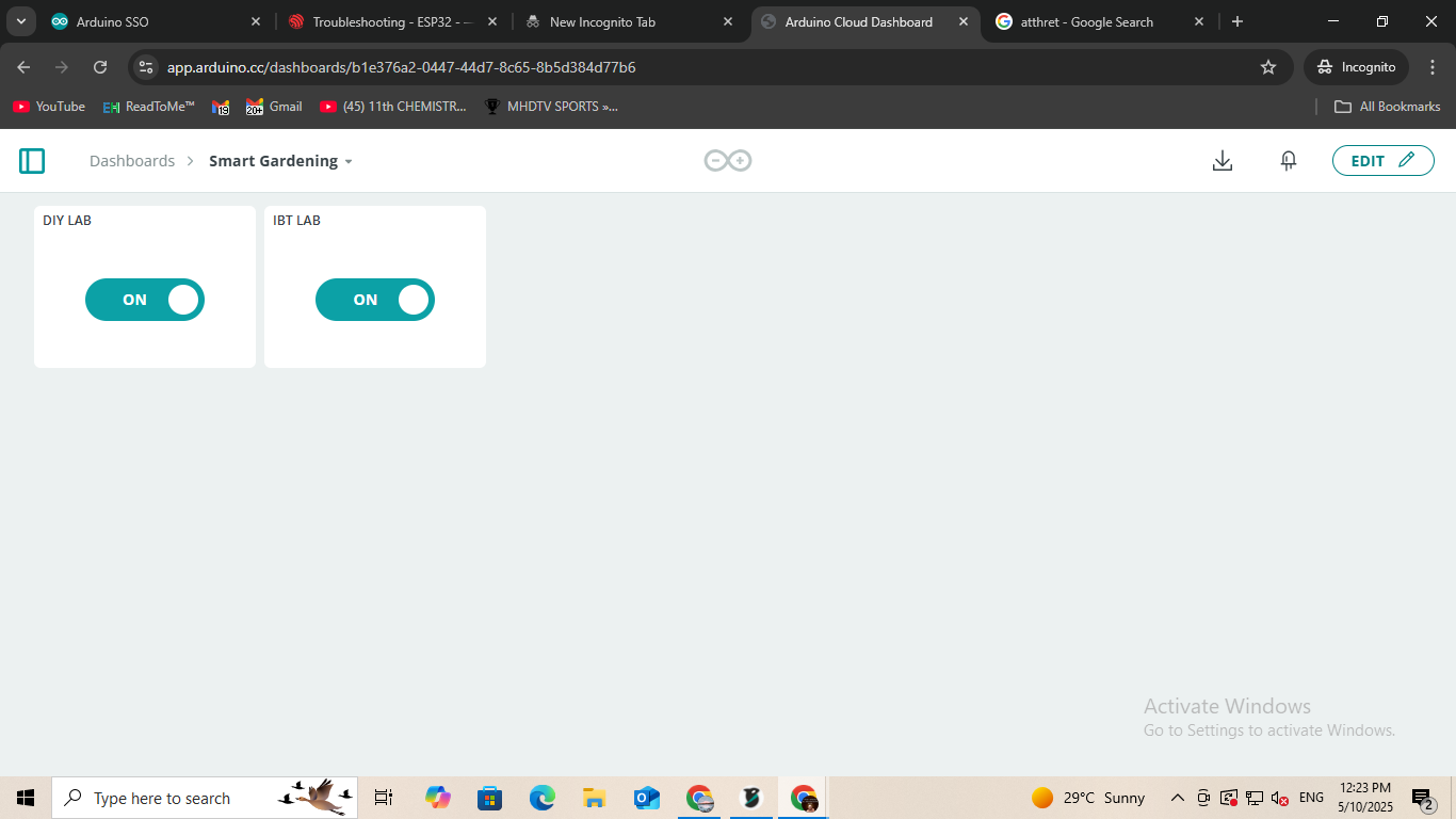
Set up corresponding dashboards for each project, each including an ON/OFF switch
widget linked to its respective variable.
Verified and configured Wi-Fi credentials, user authentication, and linked devices for
seamless connection.
Remote Control of XIAO Board Using Arduino Cloud
4. Code Upload and Device Programming
Developed and deployed the code to control the relays via the dashboards.
Steps Taken:
Wrote and uploaded the necessary Arduino sketches for both DIY LAB and IBT LAB projects.
Connected each XIAO board to the system via USB and uploaded the code individually.
Confirmed successful uploads and device synchronization with Arduino Cloud.
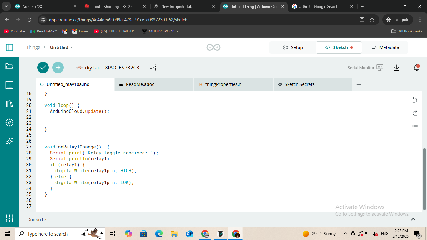
#CODE:-
1) DIY LAB
#include "thingProperties.h"
#define relay1pin D5
void setup() {
Serial.begin(115200);
delay(1500);
pinMode(relay1pin, OUTPUT);
digitalWrite(relay1pin, LOW);
initProperties();
ArduinoCloud.begin(ArduinoIoTPreferredConnection);
setDebugMessageLevel(2);
ArduinoCloud.printDebugInfo();
}
void loop() {
ArduinoCloud.update();
}
void onRelay1Change() {
Serial.print("Relay toggle received: ");
Serial.println(relay1);
if (relay1) {
digitalWrite(relay1pin, HIGH);
} else {
digitalWrite(relay1pin, LOW);
}
}
2) IBT LAB
#include "thingProperties.h"
#define relay2pin D5
void setup() {
Serial.begin(115200);
delay(1500);
pinMode(relay2pin, OUTPUT);
digitalWrite(relay2pin, LOW);
initProperties();
ArduinoCloud.begin(ArduinoIoTPreferredConnection);
setDebugMessageLevel(2);
ArduinoCloud.printDebugInfo();
}
void loop() {
ArduinoCloud.update();
}
void onRelay2Change() {
Serial.print("Relay toggle received: ");
Serial.println(relay2);
if (relay2) {
digitalWrite(relay2pin, HIGH);
} else {
digitalWrite(relay2pin, LOW);
}
}
Code for Controlling XIAO Board Using Arduino Cloud -


5. System Integration and Real-Time Testing
Integrated all hardware components and conducted real-world functionality tests.
Steps Taken:
Connected the XIAO board to the relay and linked the relay to the solenoid valve.
Powered the solenoid valve circuit using a 12V adapter to ensure stable and sufficient current.
Activated the system by switching on the control from the Arduino Cloud dashboard.
Verified that turning the switch ON enabled the relay and started water flow through the
solenoid valve.
Confirmed that switching OFF deactivated the relay, stopping the water supply.
Successfully tested the solenoid valve in a real garden water line setup to
ensure practical operability.
Testing the XIAO board using the Arduino Cloud app.
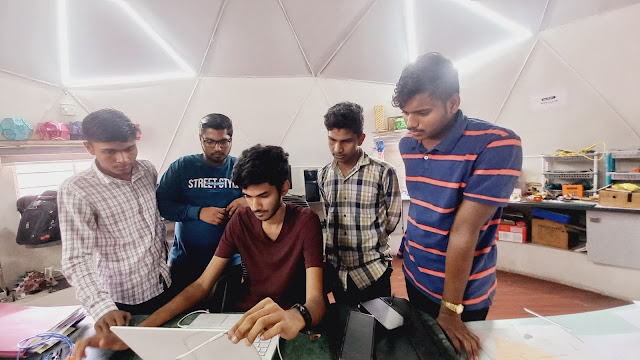
Observations & Key Findings:
The XIAO board, combined with Arduino Cloud, offers reliable and seamless remote
control capabilities.
Relays effectively managed switching of the 12V-powered solenoid valve.
Dashboards in Arduino Cloud provide a user-friendly interface for monitoring and control.
Real-time water flow testing confirmed both electrical and mechanical
functionality of the system.
ABOUT SOLIDWORK SOFTWARE
SolidWorks is a professional 3D CAD software developed by Dassault Systèmes , widely used in engineering and product design. It allows users to create detailed 3D models, assemblies, and 2D drawings with parametric features. The software supports simulation, sheet metal design, weldments, rendering, and CAM. Available in Standard, Professional, and Premium packages, SolidWorks is used across industries like automotive, aerospace, and manufacturing. It runs on Windows and offers certifications such as CSWA and CSWP for skill validation. Known for its user-friendly interface and powerful tools, SolidWorks helps engineers efficiently design, test, and produce high-quality products.
purpose of the control box
In this project, I designed a custom control box using SolidWorks to house and protect sensitive electronic components. The main goal of this control box is to shield the electronics from rain and outdoor weather conditions, ensuring long-term reliability and safety. I chose SolidWorks for this task because of its powerful 3D modeling features, ease of use, and precise control over dimensions, which are critical when designing enclosures that must be both functional and weather resistant.
design control box parts in SolidWorks

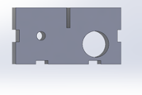


Final Box:
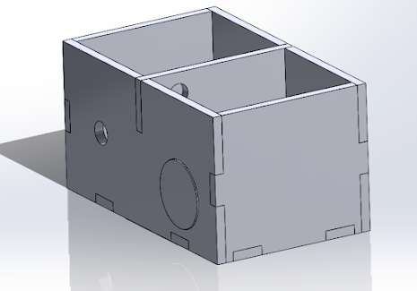
Control Box Fabrication:
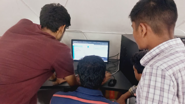
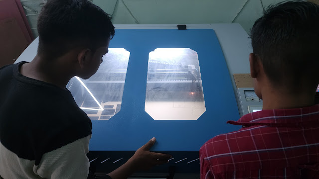
We are using a laser cutting machine to design and fabricate a custom control box.
The control box is essential for securely mounting the solenoid and Xiao board circuit, which are critical components of our system.
Laser cutting offers high precision and efficiency, allowing us to accurately shape the enclosure parts.
This ensures a perfect fit and contributes to the reliable functionality of the system.
The project provides hands-on experience in:
Hardware integration
Fabrication techniques
Circuit safety design

Clamping of Drainage Pipe:
Purpose: Clamping is done to secure the dripper pipe in place and prevent movement due to water pressure or external forces.
Stability: Ensures the dripper pipe stays firmly in position across the field or greenhouse.
Leak Prevention: Prevents pipe disconnection or leakage at joints and emitter points.
Material Used: Clamps are usually made of plastic or rust-proof metal, suitable for outdoor and wet environments.
Spacing: Clamps are installed at regular intervals (usually every 1 to 2 meters) to maintain uniform pipe alignment.
Prevents Bending: Proper clamping avoids pipe sagging or bending, which can affect water flow and dripper efficiency.
Easy Maintenance: Clamped pipes are easier to inspect, clean, and repair.
Installation: Clamps are usually fixed to
supports, stakes, or structures using screws, hooks, or clips.
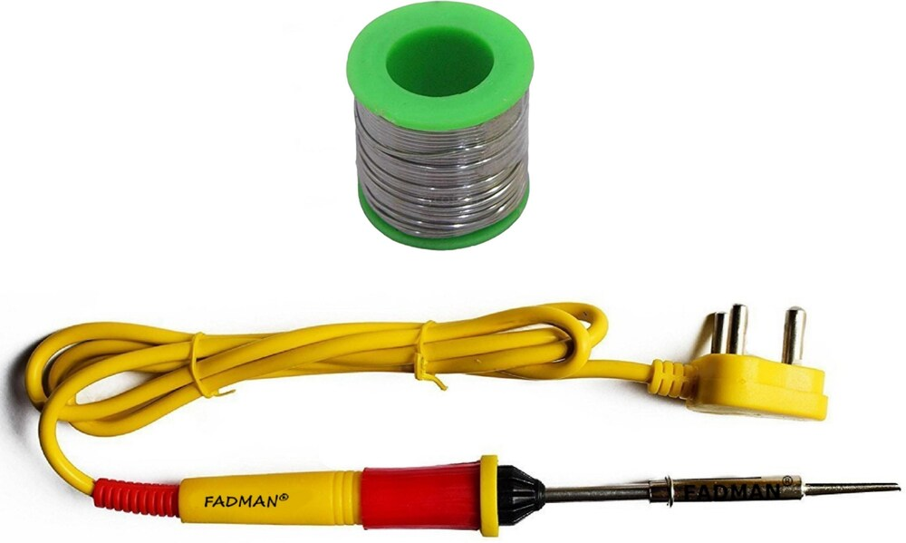
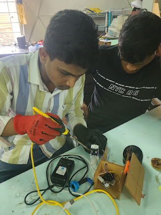
Soldering Process:
Soldering to a solenoid valve circuit involves connecting electrical wires to the solenoid coil terminals using a soldering iron and solder wire. The process must ensure a solid, conductive, and durable joint to allow proper voltage supply and valve activation.
Process:
Solenoid
Wires (preferably stranded, insulated)
Soldering iron
Solder (rosin-core recommended)
Heat shrink tubing or electrical tape
Wire stripper and cutter
Helping hands or clamps (optional but helpful)
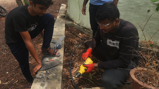
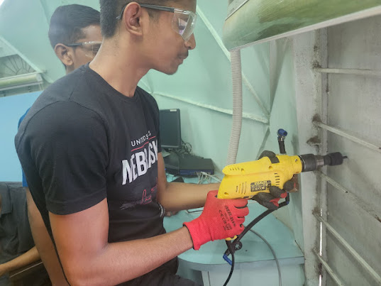
Metal Drilling :
drilled into a metal surface to create access points for both the main hose pipe and the drip irrigation pipe.
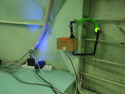
Fix Control Box to Wall


Comments
Post a Comment